
Surveying, Topography, Surfaces and Volumes Calculations
Note: this product is available in a separate version designated for ZWCAD under the name CivilCADz Standard
CivilCAD 10 Standard is a comprehensive package for surveyors, lands developers and construction companies. With the Standard, work is made simple from field data input, through COGO (coordinates geometry) and production of maps, to setting out points in an efficient and systematic method.
- Automatic creation and processing of contour lines
- Advanced and automatic solutions for handling open and closed breaklines
- Multiple presentation formats for breaklines on the drawing
- Creation of quick ground sections between any two points
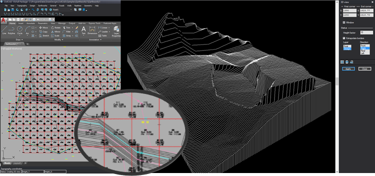
- Calculation of quantities between layers and their presentation in either earthworks grid, triangles grid, cross sections or division into lots
- Detailed quantities report production
- Wide range of solutions for handling planes (lots) and their side-slopes
- Drawing of zero line and earthworks contour lines
- Automatic alert and delete mechanism of an overlapping area between two topography surfaces
- Coordinates having exceptional data can be automatically excluded from interpolation
- Direct communication with standard compliant surveying instruments (RAW & Coordinates)
- Unique least squares traverse adjustments solutions including poly network and free network
- Superior coordinates editor for easy manipulation and filtering
- Extraction of points by filtering elements from the drawing
- Complete menu for geometric computations (COGO)
- Special feature for computing points relative to centerline
- User-defined sets of codes and their presentation as blocks in the drawing
- Special features for drawing division for plotting
- Unlimited import and export capabilities
CivilCAD 10 Standard Features
Surveying and COGO Calculations
- Intuitive and user-friendly editor for editing list of coordinates within the drawing environment (AutoCAD®; ZWCAD® and BricsCAD®). The editor includes an interactive update mechanism between the drawing and the list of coordinates in which it is displayed; any change in the editor will be updated in the drawing, and vise-versa, any new point added to the drawing will immediately appear in the editor. Furthermore, the editor includes many additional functions such as finding points by name, area and height, freezing points, massive changes to elevation in points groups and more.
- Sophisticated and convenient mechanism for computation of surveying observations including options for coordinating between numerous observations, reviewing several observations, least square traverse adjustment, working from multiple stations and full editing of the observations file. All this will be done in an ACAD environment while viewing the results instantly on the drawing, accompanied by detailed computations reports.
- Complete menu for all geometric computations (COGO) required by surveyors, such as intersections, coordinates transformations, parallel lines etc.
- Special module for computing points along centerlines that combine straight, curves and transition curves segments. The points will be calculated as station and offset, single points or by calculating a group of points from a desired station to a desired station along the centerline, by offset or number of offsets.
- Direct data exchange with all leading surveying tools in the market including Trimble, Leica, TopCon, Sokkia and more.
- Complete sets that allow working with codes in the field and their instant drawing as blocks in the drawing.
- Rapid line connections in straight lines and in arcs according to a point name, points range or codes. Breaklines definition export to breaklines file.
- Extraction of points from the drawing for setting out in the field in a simple and convenient manner and their direct transfer to the surveying tool. Optional extraction of points both, by a systematic selection of each and every point, or by filtering a group of points according to layer, window, and point type.
- A filtering module that allows to filter points by layer(s) and object types and convert them into the coordinates list. The module allows to add points names and elevations from different layers using texts and attributes.
Frames Maker
An all-inclusive module for division of the drawing into sheets (layouts) in any desirable scale and paper size. Users can select the scale, paper size (from a list of ISO paper sizes or custom size), the table/legend and the north arrow blocks. Then, users can create their own division using frames (rectangle polylines) located on the drawing in any desired position or rotation. The sheets will be generated in layout(s) which are aligned to the north in either a single or multiple layouts. Processing and creation of breaklines throughout a dynamic changing of the contour lines during the lines processing, export of the lines to a separate file, separation to open breaklines, or breaklines defining areas not for calculation (structures etc.), presentation of breaklines in multiple forms (cliff, slope) etc.
Surfaces and Topography Contour Lines
- Creation of 3D surfaces as BIM (Building Information Modeling) objects – Working with 3D models displaying the models’ perspectives, working with both existing and design models simultaneously, instant display of existing or designed calculated elevation at any location by a mouse click and more.
- Creation and processing of contour lines including automatic elevation labeling (in uphill direction) and an option to complete the elevation labeling in specific locations. More options include division of the contour lines into layers – automatic or according to user selection.
- Processing and creation of breaklines throughout a dynamic changing of the contour lines during the lines processing, export of the lines to a separate file, separation to open or closed breaklines defining areas not for calculation (structures etc.), presentation of breaklines in multiple forms (cliff, slope) etc.
- Definition of contour lines/surfaces’ borders in numerous fashions – by a convex hull, automatic “fix-borders” function, definition of minimum distance for interpolation or defining a border according to a border-line.
- Automatic alert and delete mechanism of an overlapping area between two topography surfaces.
- Coordinates having exceptional data can be automatically excluded from interpolation.
- Creation of quick ground sections between any two given points including existing status, designed status and a data table. Option for receiving sections in any desired scale to the length and to the height.
- Drawing of zero line and earthworks contour lines for both planes design and computation of earthworks between layers. The tools above, along with the features in CivilCAD 10 Survey, turn CivilCAD 10 Standard to the most attractive design software in the market today, and the only one to match market standards set by authorities (municipalities) and clients worldwide.
Land Development and Quantities Calculations
- Volumes calculations between surfaces in various methods – “accurate system”, earthworks grid, triangles grid, cross sections, or division into lots. Each calculation will be displayed on the drawing in layers and attached with a detailed quantities report which can be printed or exported to Excel.
- Drawing of a zero line and earthworks contour lines (+/-) in any desired interval and various layers and formats.
- Land development using planes (lots); defining the planes as BIM objects using their borders, defining planes elevations using border points or baseline and slope, defining side slopes in cut and fill and an option for defining multiple slopes for the same plane. Each plane is a separated BIM – users can display its area and volumes, designed contour lines, data on border points and more.
More information about CivilCAD Standard can be found in the tutorials here